Description
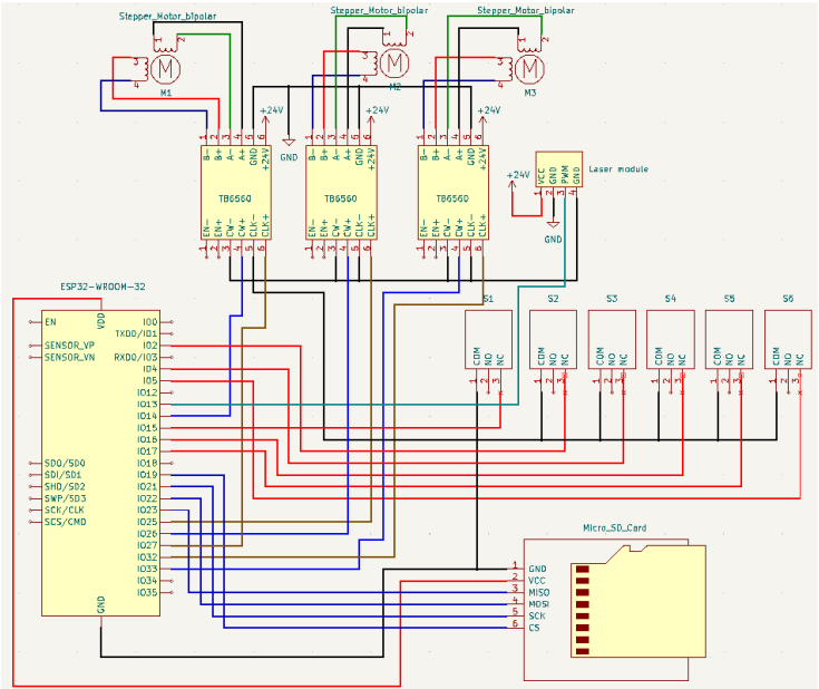
Controller Board
ESP32 WROOM 32 with TB6560 motor drivers.
Machine Description
Laser engraver with 2 motors for Y axis and one for X axis driven with TB6560.
Input Circuits
https://imgur.com/a/s3vCA2U
Configuration file
name: "ESP32 Dev Controller V4"
board: "ESP32 Dev Controller V4"

stepping:
  engine: RMT
  idle_ms: 255
  dir_delay_us: 0
  pulse_us: 4
  disable_delay_us: 0

axes:
  x:
    steps_per_mm: 800
    max_rate_mm_per_min: 2000
    acceleration_mm_per_sec2: 25
    max_travel_mm: 3500
    soft_limits: false
    homing:
      cycle: 1
      allow_single_axis: true
      positive_direction: false
      mpos_mm: 10.00
      feed_mm_per_min: 100.000
      seek_mm_per_min: 200.000
      settle_ms: 500
      seek_scaler: 1.100
      feed_scaler: 1.100
    motor0: #X1
      limit_neg_pin: gpio.17:high
      limit_pos_pin: gpio.5:high
      hard_limits: true
      pulloff_mm: 0.500
      standard_stepper:
        step_pin: gpio.32
        direction_pin: gpio.33

  y:
    steps_per_mm: 800
    max_rate_mm_per_min: 2000
    acceleration_mm_per_sec2: 25
    max_travel_mm: 3500
    soft_limits: false
    homing:
      cycle: 2
      allow_single_axis: true
      positive_direction: false
      mpos_mm: 10.00
      feed_mm_per_min: 100.000
      seek_mm_per_min: 200.000
      settle_ms: 500
      seek_scaler: 1.100
      feed_scaler: 1.100
    motor0: #Y2
      limit_neg_pin: gpio.4:high
      limit_pos_pin: gpio.16:high
      hard_limits: true
      pulloff_mm: 0.500
      standard_stepper:
        step_pin: gpio.25
        direction_pin: gpio.26
    motor1: #Y1
      limit_neg_pin: gpio.15:high
      limit_pos_pin: gpio.2:high
      hard_limits: true
      pulloff_mm: 0.500
      standard_stepper:
        step_pin: gpio.27
        direction_pin: gpio.14:low

spi:
  miso_pin: gpio.23
  mosi_pin: gpio.22
  sck_pin: gpio.21

sdcard:
  cs_pin: gpio.19
  card_detect_pin: NO_PIN


Laser:
  pwm_hz: 5000
  output_pin: gpio.12
  enable_pin: NO_PIN
  disable_with_s0: false
  s0_with_disable: true
  tool_num: 0
  speed_map: 0=0.000% 255=100.000%
Startup Messages
[MSG:INFO: FluidNC v3.6.8]
[MSG:INFO: Compiled with ESP32 SDK:v4.4.1-1-gb8050b365e]
[MSG:INFO: Local filesystem type is spiffs]
[MSG:INFO: Configuration file:config.yaml]
[MSG:INFO: Machine ESP32 Dev Controller V4]
[MSG:INFO: Board ESP32 Dev Controller V4]
[MSG:INFO: SPI SCK:gpio.21 MOSI:gpio.22 MISO:gpio.23]
[MSG:INFO: SD Card cs_pin:gpio.19 detect:NO_PIN freq:0]
[MSG:INFO: Stepping:RMT Pulse:4us Dsbl Delay:0us Dir Delay:0us Idle Delay:255ms]
[MSG:INFO: Axis count 3]
[MSG:INFO: Axis X (10.000,3510.000)]
[MSG:INFO:   Motor0]
[MSG:INFO:     standard_stepper Step:gpio.32 Dir:gpio.33 Disable:NO_PIN]
[MSG:INFO:  X Neg Limit gpio.17]
[MSG:INFO:  X Pos Limit gpio.5]
[MSG:INFO: Axis Y (10.000,3510.000)]
[MSG:INFO:   Motor0]
[MSG:INFO:     standard_stepper Step:gpio.25 Dir:gpio.26 Disable:NO_PIN]
[MSG:INFO:  Y Neg Limit gpio.4]
[MSG:INFO:  Y Pos Limit gpio.16]
[MSG:INFO:   Motor1]
[MSG:INFO:     standard_stepper Step:gpio.27 Dir:gpio.14:low Disable:NO_PIN]
[MSG:INFO:  Y2 Neg Limit gpio.15]
[MSG:INFO:  Y2 Pos Limit gpio.2]
[MSG:INFO: Axis Z (-1000.000,0.000)]
[MSG:INFO:   Motor0]
[MSG:INFO: Kinematic system: Cartesian]
[MSG:INFO: Laser Ena:NO_PIN Out:gpio.12 Freq:5000Hz Period:8191]
[MSG:INFO: Using spindle Laser]
[MSG:INFO: Connecting to STA SSID:TP-LINK_8452]
[MSG:INFO: Connecting.]
[MSG:INFO: Connecting..]
[MSG:INFO: Connected - IP is 192.168.0.107]
[MSG:INFO: WiFi on]
[MSG:INFO: Start mDNS with hostname:http://fluidnc.local/]
[MSG:INFO: SSDP Started]
[MSG:INFO: HTTP started on port 80]
[MSG:INFO: Telnet started on port 23]
User Interface Software
FluidTerm, WebUI
What happened?
Nothing seems to work, limit swith LED is not even turning on. When using version 3.3.1 everything is working fine. No errors given when starting machine
Other Information
No response


Activity
Skorpi08 commented on Mar 26, 2023
you can add Pics by drag&drop
MitchBradley commented on Mar 26, 2023
Your limit switches do not have any external pullups, and the internal pullups are not enabled due to no “:pu” attributes on the pins.
Aljo003 commented on Mar 26, 2023
Should I keep :high attributes or only add :pu ?
MitchBradley commented on Mar 26, 2023
Either is okay. :high is the default, so :pu and :high:pu are the same
Aljo003 commented on Mar 26, 2023
Now limits switch LED is working and it’s reporting in $limits but it’s not triggering alarm when pressed, homing is not working too.
MitchBradley commented on Mar 26, 2023
http://wiki.fluidnc.com/en/support/help_with_switch_problems
See especially the “Debug Mode” section
Aljo003 commented on Mar 26, 2023
Oh wait i also have wrong config file, i’m sending new one with modified switches
Aljo003 commented on Mar 26, 2023
When it hits limit switch when homing and it’s just spamming this
MitchBradley commented on Mar 26, 2023
What kind of switches?
Aljo003 commented on Mar 26, 2023
Connected to NC
MitchBradley commented on Mar 26, 2023
When it hits the switch, try pushing it in manually then releasing it to see what happens
Aljo003 commented on Mar 26, 2023
It’s still in Homing mode but motor stop and when I hold switch same thing is spamming
Aljo003 commented on Mar 26, 2023
And also Laser is not working, SD Card is not detected
MitchBradley commented on Mar 26, 2023
Show a photograph of your system, not a schematic.
Aljo003 commented on Mar 26, 2023
14 remaining items
MitchBradley commented on Mar 27, 2023
Something could be wrong with the wiring to the x switch.
MitchBradley commented on Mar 27, 2023
bad ground perhaps?
MitchBradley commented on Mar 27, 2023
Did you put RC filters with external pullups on the switches? Until you do that, the signal quality will be so bad that I cannot help you.
Aljo003 commented on Mar 27, 2023
I didn’t yet because i need to get capacitors and resistors to build RC filters. I will make that and will see if it will work then. But it’s strange that will older version it’s working fine. Thanks for help
MitchBradley commented on Mar 27, 2023
The older version uses a different method for reading inputs. The old method was very slow and could miss fast transitions.
MitchBradley commented on Mar 27, 2023
Software improvements can often reveal hidden hardware problems.
Aljo003 commented on Mar 27, 2023
Okay, I will make RC filters first, grounds on switches are okay.
Aljo003 commented on Mar 27, 2023
I now tried putting limit switch wires as far away as i could from motor wires and machine homing was succesfull. I will add RC filters and test it then. Thanks for your help
Aljo003 commented on Mar 27, 2023
Can I also fix interference with ferrite bead as if would be easier? Or are R/C filters still better then ferrite bead?
MitchBradley commented on Mar 27, 2023
Rc is the common solution. You will just have to experiment. I cannot predict exactly what will happen in your setup. There are many aspects of your setup that are hobbyist grade not industrial grade. Despite the fact that were have EE training and experience, we are volunteer software developers, not paid EE consultants or teachers.
Aljo003 commented on Mar 29, 2023
Okay,thanks for your help, I managed to get capacitors and resistors and will make RC filters this week and try it, is it okay if I wire all capacitors to one wire and that wire to one ground and same with resistor and then i just wire that wire between each resistor and capacitor to limit switch pin?
MitchBradley commented on Mar 29, 2023
I repeat, we are not EE consultants.
PatrikRindlisbacher commented on Mar 29, 2023
You can find good instructions on the net for RC filters.
Important short lines away from the entrance. –> less than 10mm are desired.
Aljo003 commented on Apr 2, 2023
I added RC filters and now its working fine, thanks for your help
closed this as completedon Apr 2, 2023