Limit switches help CNC machine equipment prevent movement beyond the physical limits of an axis.
There are 2 methods to limit machine movement using limit switches:
1. Enable hard limits – when your movement triggers a limit signal, the system stops movement and issues a hard limit alarm.
2. Use soft limits – use limit switches as mechanical home reference points, then software limits movement through the maximum travel parameters set for each axis.
Limit Switch Wiring #
Limit switches support normally open or normally closed configurations. Normally closed (NC) switches are recommended. The system supports mechanical, photoelectric, proximity and other switch inputs. Regardless of switch type, a low-level signal on the limit input is considered a triggered limit signal. Therefore, only NPN type switches are supported.
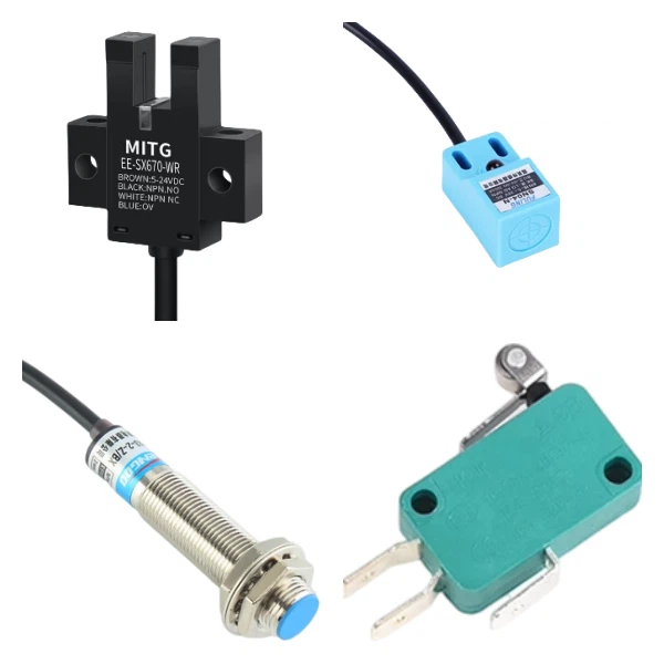
Limit switches are generally divided into mechanical contact closure types, or photoelectric sensing and metal sensing types.
Mechanical switches output signals through mechanical contact and engagement.
Photoelectric sensing – outputs signal when light source is blocked by an object.
Metal sensing – outputs signal when contact with metal is detected.
Photoelectric and metal sensing switches typically have 4 wires: 2 wires for power supply positive and negative to power the device itself (usually 5-24V), and the remaining 2 for normally open/normally closed signal output.
Please do not use 5V power supply for limit switches, as it may not trigger the controller’s limit input signal.
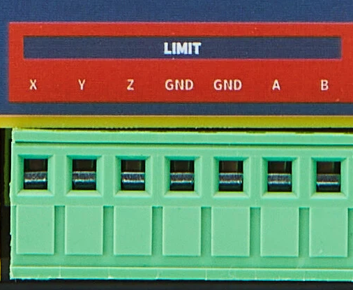
The limit input interfaces for each axis on the controller are located here:
Below are 4 common types of limit switches available on the market and their connection methods:
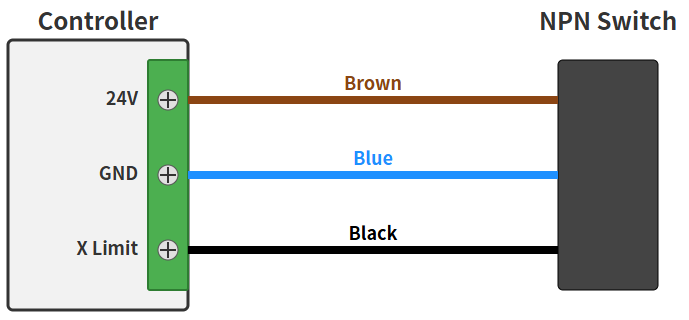
Note: The wiring above is based on brown = VCC, blue = GND, and black = signal output. If yours differs, please adjust accordingly.
Installing Limit Switches #
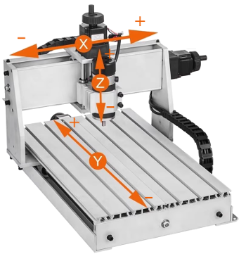
You can install limit switches anywhere along an axis, but typically at the physical limit positions at the ends of the axis.
Limit/Homing Parameter Settings #
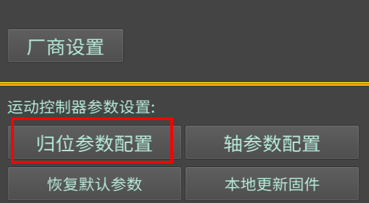
In the <Settings> homing parameter configuration:
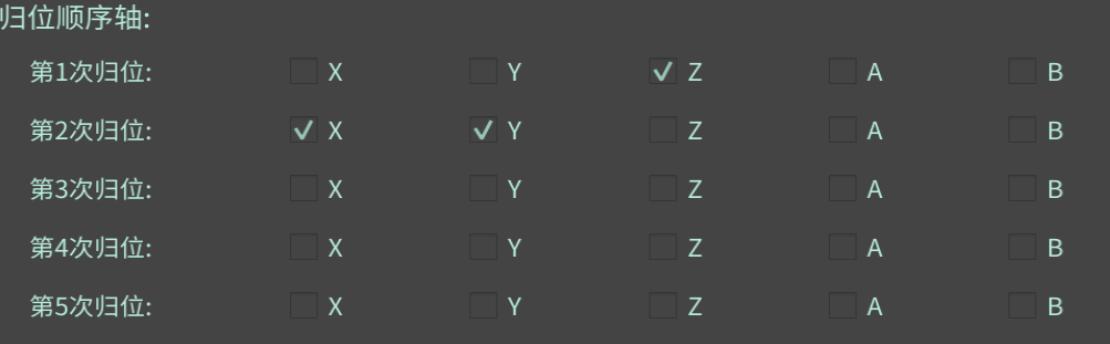
The homing sequence axis setting is for the full homing command $H. The system will home in the order you specify, up to 5 times.
Typically home the Z-axis first to avoid crashes. (Currently there seems to be a bug when homing multiple axes simultaneously – please select only one axis per homing step for now.)
Remaining parameter descriptions:
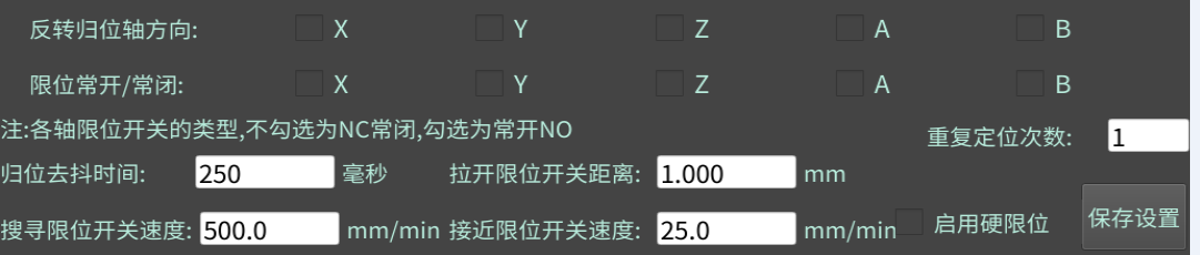
Invert homing axis direction – if when homing an axis, the search movement direction is opposite to your actual installation, you can set this parameter.
The system supports connecting normally open or normally closed limit switches. Please ensure the physical connection type matches the limit NO/NC setting.
Pull-off distance from limit switch refers to how far to move in the opposite direction after triggering a limit to clear the limit signal.
Performing Homing #
Homing can be divided into full homing (following the 5-step homing sequence set above) or single-axis homing.
Command $H is for full homing, which homes all axes in the order specified in the homing sequence settings.
Command $H + axis letter, such as $HX, homes a single axis individually.
It is recommended to first enable hard limits and manually trigger the limit switch to see if the system’s hard limit alarm is triggered, or check the limit signal information in the 3D interface.
Then try single-axis homing. Once that works correctly, try full sequential homing.
Enter the above commands in the MDI interface to experiment and familiarize yourself.
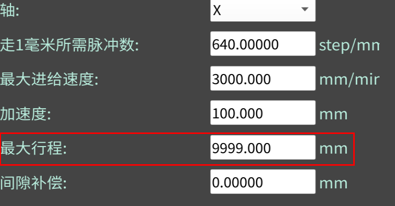
Finally, each axis has a maximum travel parameter setting. After you home an axis,
the system will use this parameter to software-limit your movement, preventing exceeding physical limits.
Note: if you modify this value after homing, the homing status will be reset to invalid. Please perform homing again.