The controller supports 0~10V analog voltage signal output for controlling the spindle speed of the VFD (Variable Frequency Drive),
as well as M3 and M4 signals for controlling the spindle rotation direction.
If you have a regular spindle (controlled only via a switching power supply), please refer to Output Port Control Relay and use the M3 spindle switch port for control.
If you are using a laser,
or a switched spindle with speed control via a MOSFET, connect the PWM signal and share GND with the controller.
The relevant terminal positions are shown in the figure below:
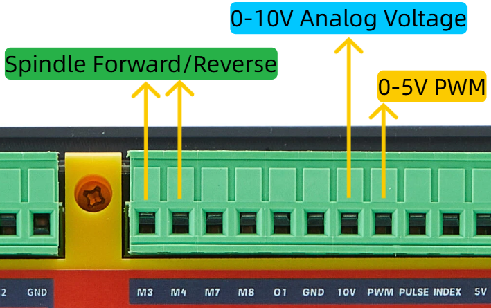
Note: The 0-10V analog voltage is converted from a 0-5V PWM signal through an operational amplifier.
Wiring Examples #
Note: VFDs on the market vary widely, but the control principles and methods are generally the same.
To control a VFD, you need to configure the relevant parameters on the VFD.
You cannot simply wire the connections shown in the examples below to the controller
and expect to control the VFD and spindle motor.
If you are new to VFDs and spindle motors,
we strongly recommend contacting your VFD’s technical support,
learning and familiarizing yourself with the VFD parameter settings,
and manually controlling the spindle rotation via the VFD panel before attempting to connect it to our controller.
Below is a wiring example for the VFD and controller:
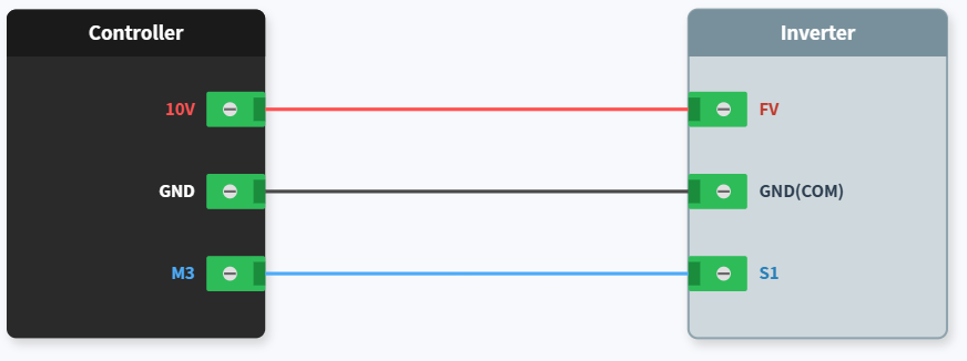
Here we have configured the VFD to control the spindle speed via the terminal analog voltage (FV), i.e., 0-10V voltage.
Note that the analog voltage input terminal label on different VFD brands may not necessarily be “FV”.
The S1 terminal here is the forward rotation input control signal for the spindle, which we have already configured through the VFD settings.
Additionally, the VFD GND terminal — sometimes labeled COM — is the same thing.


