Installing the A4988/2209 Modules #
The control board comes with 4 module sockets. You can use A4988/2209 modules to drive small stepper motors.
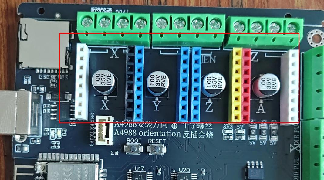
The installation orientation is determined by the cross-head screw on top of the module. The image below shows an installation example for the A4988 module; the 2209 module is installed the other way around.
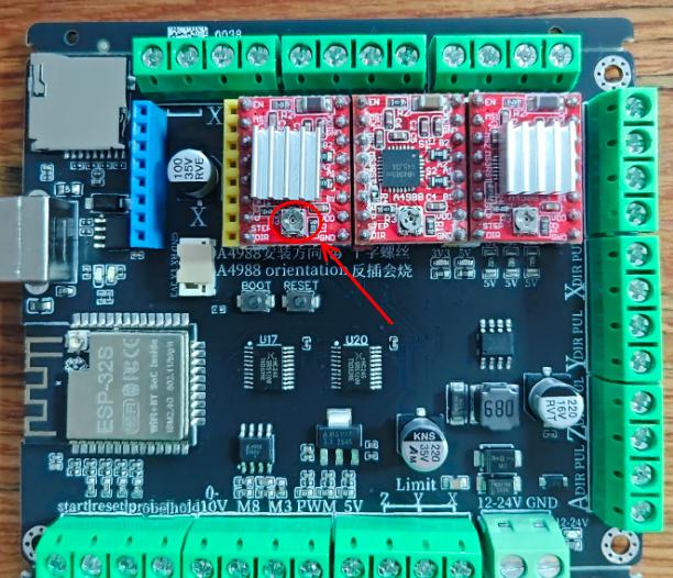
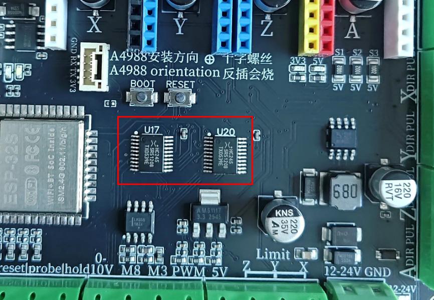
If the module is installed in the wrong orientation and a 12-24V power supply is connected, the 74HC245 pin protection chip of the ESP32 will be damaged.
The ESP32 module itself will not be damaged, but it will no longer be able to output the pulse/direction signals for each axis.
You can replace the damaged protection chip yourself.
Note that there are some other stepper driver modules available on the market. These modules have not been tested, so please do not use them, in order to avoid damaging the module.
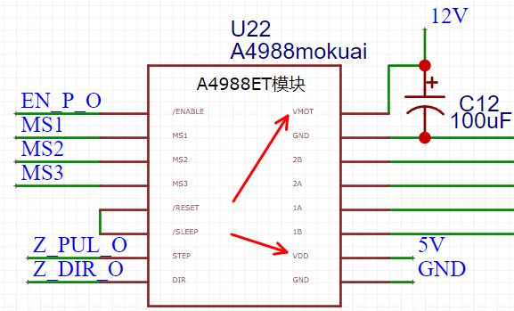
The installation orientation of a module is determined by its power connector. Take the A4988 module as an example.
It has 2 power inputs: one is 5V and the other is a 12-24V input. On the A4988 it is labeled VMOT, which is the power supply used to drive the stepper motor.
We use the VMOT position as the reference for the installation orientation. On the control board, VMOT is the first pin on the right.
If the module is installed in the wrong orientation, the 12-24V on the control board will break down the A4988 chip, and in turn break down the pulse/direction outputs of the control board, i.e. the 74HC245 chip mentioned above.
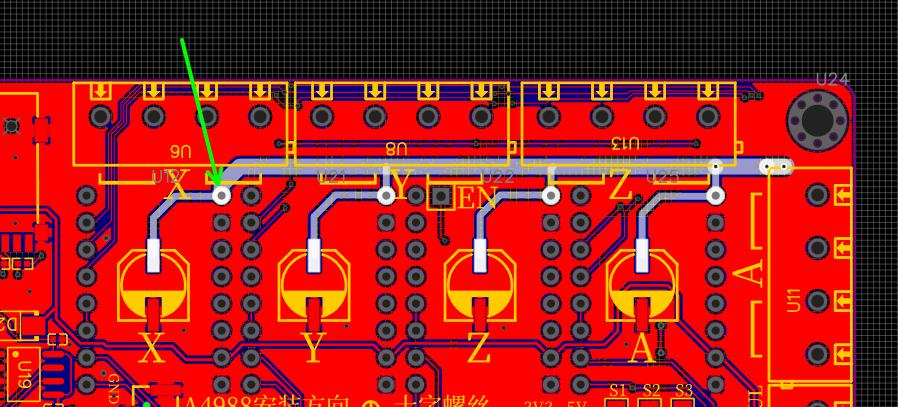
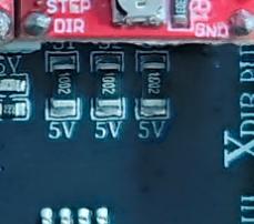
The microstepping pins MS1, MS2 and MS3 of the module socket are permanently pulled up to 5V through 10K resistors and the microstepping cannot be adjusted, so the A4988 microstepping is fixed at 16, and the 2209 microstepping is fixed at 16.
If you really need to adjust the microstepping, you can remove those resistors and connect S1, S2 and S3 directly to 5V or GND.
Installing the Stepper Motors #
The motor connectors of the modules are located here.
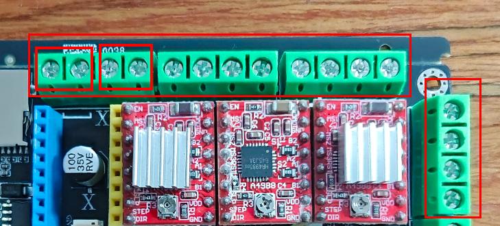
On the terminal block of each axis, the 2 left terminals and the 2 right terminals each form one winding.
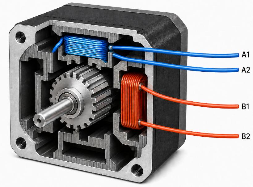
A typical stepper motor has 4 wires, that is, 2 windings, which means 2 of the wire ends belong to the same winding, and so do the other 2.
You can identify them using the continuity (buzzer) mode of a multimeter, then connect any 2 wires that are electrically connected to the left side, and the other 2 connected wires to the right side.
If this is still unclear, refer to the diagram below:
Controlling Motor Movement from the Host Software #
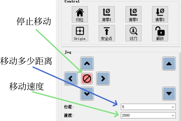
Once all the wiring is done, we can connect the host software and manually control the rotation of the stepper motors.
Taking Candle2 as an example, the up/down/left/right buttons on the right side are used to manually control the movement of the machine.
Setting the Correct Steps per Millimeter #
Although you are now able to control the movement of the machine from the host software, it may not move exactly the expected distance.
After connecting the stepper motors, you still need to configure the relevant parameters to make sure the machine moves accurately, because GRBL needs to know how many pulses to send in order to move the machine 1 millimeter.
For details, please refer to the steps-per-millimeter configuration section of ESP32_GRBL System Parameter Settings and Description.


